Draw a Circle and Color It Red
Applying styles and colors
- « Previous
- Next »
In the chapter almost drawing shapes, we used only the default line and fill up styles. Hither nosotros will explore the canvas options we have at our disposal to make our drawings a piffling more attractive. Y'all volition larn how to add different colors, line styles, gradients, patterns and shadows to your drawings.
Colors
Up until now we accept only seen methods of the drawing context. If we want to apply colors to a shape, there are two important properties we can apply: fillStyle and strokeStyle.
-
fillStyle = color -
Sets the mode used when filling shapes.
-
strokeStyle = color -
Sets the style for shapes' outlines.
color is a string representing a CSS <color>, a gradient object, or a pattern object. We'll look at gradient and pattern objects later. By default, the stroke and make full color are set to black (CSS color value #000000).
Note: When you set the strokeStyle and/or fillStyle property, the new value becomes the default for all shapes being drawn from then on. For every shape you want in a different color, you will demand to reassign the fillStyle or strokeStyle property.
The valid strings yous can enter should, according to the specification, be CSS <colour> values. Each of the following examples describe the aforementioned color.
// these all set the fillStyle to 'orange' ctx.fillStyle = 'orange' ; ctx.fillStyle = '#FFA500' ; ctx.fillStyle = 'rgb(255, 165, 0)' ; ctx.fillStyle = 'rgba(255, 165, 0, 1)' ; A fillStyle case
In this example, nosotros once again utilise two for loops to depict a grid of rectangles, each in a unlike color. The resulting image should look something like the screenshot. In that location is nothing too spectacular happening hither. We use the two variables i and j to generate a unique RGB color for each foursquare, and merely modify the scarlet and green values. The blue channel has a fixed value. By modifying the channels, you lot tin generate all kinds of palettes. By increasing the steps, you can achieve something that looks like the color palettes Photoshop uses.
function draw ( ) { var ctx = certificate. getElementById ( 'canvas' ) . getContext ( '2d' ) ; for ( var i = 0 ; i < 6 ; i++ ) { for ( var j = 0 ; j < 6 ; j++ ) { ctx.fillStyle = 'rgb(' + Math. floor ( 255 - 42.5 * i) + ', ' + Math. floor ( 255 - 42.v * j) + ', 0)' ; ctx. fillRect (j * 25 , i * 25 , 25 , 25 ) ; } } } The result looks similar this:
A strokeStyle example
This example is similar to the one to a higher place, but uses the strokeStyle property to alter the colors of the shapes' outlines. Nosotros use the arc() method to depict circles instead of squares.
function draw ( ) { var ctx = document. getElementById ( 'canvass' ) . getContext ( '2d' ) ; for ( var i = 0 ; i < 6 ; i++ ) { for ( var j = 0 ; j < 6 ; j++ ) { ctx.strokeStyle = 'rgb(0, ' + Math. floor ( 255 - 42.5 * i) + ', ' + Math. floor ( 255 - 42.v * j) + ')' ; ctx. beginPath ( ) ; ctx. arc ( 12.five + j * 25 , 12.5 + i * 25 , ten , 0 , Math. PI * two , true ) ; ctx. stroke ( ) ; } } } The upshot looks similar this:
Transparency
In improver to drawing opaque shapes to the canvas, we can also describe semi-transparent (or translucent) shapes. This is done by either setting the globalAlpha property or by assigning a semi-transparent color to the stroke and/or fill fashion.
-
globalAlpha = transparencyValue -
Applies the specified transparency value to all future shapes drawn on the canvass. The value must be between 0.0 (fully transparent) to i.0 (fully opaque). This value is 1.0 (fully opaque) by default.
The globalAlpha property tin be useful if you desire to draw a lot of shapes on the canvas with similar transparency, merely otherwise it'south by and large more useful to set the transparency on individual shapes when setting their colors.
Because the strokeStyle and fillStyle properties take CSS rgba color values, we can use the post-obit note to assign a transparent color to them.
// Assigning transparent colors to stroke and fill up style ctx.strokeStyle = 'rgba(255, 0, 0, 0.v)' ; ctx.fillStyle = 'rgba(255, 0, 0, 0.v)' ; The rgba() office is similar to the rgb() function simply it has one extra parameter. The last parameter sets the transparency value of this particular color. The valid range is again between 0.0 (fully transparent) and 1.0 (fully opaque).
A globalAlpha example
In this example, we'll draw a background of four dissimilar colored squares. On superlative of these, we'll draw a ready of semi-transparent circles. The globalAlpha holding is gear up at 0.2 which volition be used for all shapes from that point on. Every footstep in the for loop draws a set of circles with an increasing radius. The terminal issue is a radial gradient. By overlaying always more circles on top of each other, we effectively reduce the transparency of the circles that have already been drawn. By increasing the stride count and in effect cartoon more than circles, the background would completely disappear from the center of the prototype.
function describe ( ) { var ctx = certificate. getElementById ( 'sail' ) . getContext ( '2d' ) ; // describe groundwork ctx.fillStyle = '#FD0' ; ctx. fillRect ( 0 , 0 , 75 , 75 ) ; ctx.fillStyle = '#6C0' ; ctx. fillRect ( 75 , 0 , 75 , 75 ) ; ctx.fillStyle = '#09F' ; ctx. fillRect ( 0 , 75 , 75 , 75 ) ; ctx.fillStyle = '#F30' ; ctx. fillRect ( 75 , 75 , 75 , 75 ) ; ctx.fillStyle = '#FFF' ; // set transparency value ctx.globalAlpha = 0.2 ; // Draw semi transparent circles for ( var i = 0 ; i < vii ; i++ ) { ctx. beginPath ( ) ; ctx. arc ( 75 , 75 , x + 10 * i, 0 , Math. PI * 2 , true ) ; ctx. make full ( ) ; } } An example using rgba()
In this second case, we do something like to the one in a higher place, but instead of drawing circles on top of each other, I've drawn small rectangles with increasing opacity. Using rgba() gives yous a footling more control and flexibility because we tin prepare the fill and stroke mode individually.
part describe ( ) { var ctx = document. getElementById ( 'canvas' ) . getContext ( 'second' ) ; // Draw background ctx.fillStyle = 'rgb(255, 221, 0)' ; ctx. fillRect ( 0 , 0 , 150 , 37.5 ) ; ctx.fillStyle = 'rgb(102, 204, 0)' ; ctx. fillRect ( 0 , 37.5 , 150 , 37.five ) ; ctx.fillStyle = 'rgb(0, 153, 255)' ; ctx. fillRect ( 0 , 75 , 150 , 37.v ) ; ctx.fillStyle = 'rgb(255, 51, 0)' ; ctx. fillRect ( 0 , 112.5 , 150 , 37.5 ) ; // Describe semi transparent rectangles for ( var i = 0 ; i < 10 ; i++ ) { ctx.fillStyle = 'rgba(255, 255, 255, ' + (i + 1 ) / 10 + ')' ; for ( var j = 0 ; j < 4 ; j++ ) { ctx. fillRect ( five + i * 14 , 5 + j * 37.5 , xiv , 27.5 ) ; } } } Line styles
There are several properties which allow u.s. to way lines.
-
lineWidth = value -
Sets the width of lines drawn in the hereafter.
-
lineCap = type -
Sets the advent of the ends of lines.
-
lineJoin = type -
Sets the appearance of the "corners" where lines meet.
-
miterLimit = value -
Establishes a limit on the miter when 2 lines join at a sharp angle, to let you control how thick the junction becomes.
-
getLineDash() -
Returns the current line dash pattern assortment containing an even number of non-negative numbers.
-
setLineDash(segments) -
Sets the current line nuance pattern.
-
lineDashOffset = value -
Specifies where to start a nuance array on a line.
You'll become a better agreement of what these practice past looking at the examples below.
A lineWidth example
This property sets the current line thickness. Values must be positive numbers. By default this value is gear up to 1.0 units.
The line width is the thickness of the stroke centered on the given path. In other words, the area that's fatigued extends to half the line width on either side of the path. Because canvas coordinates do non direct reference pixels, special care must be taken to obtain crisp horizontal and vertical lines.
In the example below, 10 straight lines are fatigued with increasing line widths. The line on the far left is 1.0 units wide. However, the leftmost and all other odd-integer-width thickness lines do not appear crisp, because of the path's positioning.
office depict ( ) { var ctx = document. getElementById ( 'canvas' ) . getContext ( '2d' ) ; for ( var i = 0 ; i < 10 ; i++ ) { ctx.lineWidth = 1 + i; ctx. beginPath ( ) ; ctx. moveTo ( 5 + i * xiv , 5 ) ; ctx. lineTo ( 5 + i * 14 , 140 ) ; ctx. stroke ( ) ; } } Obtaining well-baked lines requires understanding how paths are stroked. In the images below, the grid represents the sail coordinate filigree. The squares between gridlines are actual on-screen pixels. In the first grid paradigm below, a rectangle from (2,ane) to (5,5) is filled. The entire area between them (light crimson) falls on pixel boundaries, and then the resulting filled rectangle volition accept crisp edges.
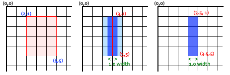
If you lot consider a path from (3,i) to (3,5) with a line thickness of one.0, you lot end up with the situation in the second image. The actual surface area to be filled (dark blueish) only extends halfway into the pixels on either side of the path. An approximation of this has to be rendered, which means that those pixels beingness only partially shaded, and results in the unabridged expanse (the low-cal blue and dark blue) being filled in with a color just half as dark as the actual stroke colour. This is what happens with the i.0 width line in the previous example code.
To gear up this, you accept to be very precise in your path cosmos. Knowing that a 1.0 width line will extend half a unit to either side of the path, creating the path from (3.5,1) to (3.5,5) results in the situation in the 3rd prototype—the i.0 line width ends up completely and precisely filling a unmarried pixel vertical line.
Note: Exist aware that in our vertical line example, the Y position withal referenced an integer gridline position—if it hadn't, nosotros would see pixels with half coverage at the endpoints (but notation likewise that this behavior depends on the current lineCap fashion whose default value is butt; you may want to compute consequent strokes with half-pixel coordinates for odd-width lines, by setting the lineCap fashion to square, so that the outer edge of the stroke around the endpoint volition be automatically extended to encompass the whole pixel exactly).
Note also that merely offset and final endpoints of a path are afflicted: if a path is closed with closePath(), there's no start and final endpoint; instead, all endpoints in the path are connected to their attached previous and side by side segment using the current setting of the lineJoin manner, whose default value is miter, with the effect of automatically extending the outer borders of the connected segments to their intersection point, so that the rendered stroke will exactly cover full pixels centered at each endpoint if those continued segments are horizontal and/or vertical. Run into the next ii sections for demonstrations of these additional line styles.
For even-width lines, each half ends upwards being an integer corporeality of pixels, so you desire a path that is between pixels (that is, (three,i) to (3,5)), instead of down the middle of pixels.
While slightly painful when initially working with scalable second graphics, paying attention to the pixel filigree and the position of paths ensures that your drawings will look right regardless of scaling or any other transformations involved. A one.0-width vertical line drawn at the right position volition become a well-baked 2-pixel line when scaled up by 2, and volition appear at the correct position.
A lineCap case
The lineCap property determines how the end points of every line are drawn. There are three possible values for this property and those are: butt, circular and square. By default this belongings is set up to barrel:
-
butt -
The ends of lines are squared off at the endpoints.
-
round -
The ends of lines are rounded.
-
square -
The ends of lines are squared off by adding a box with an equal width and half the top of the line's thickness.
In this example, nosotros'll draw three lines, each with a dissimilar value for the lineCap property. I also added two guides to come across the exact differences between the iii. Each of these lines starts and ends exactly on these guides.
The line on the left uses the default butt option. You'll notice that it's drawn completely affluent with the guides. The second is gear up to use the circular selection. This adds a semicircle to the stop that has a radius half the width of the line. The line on the right uses the foursquare option. This adds a box with an equal width and half the tiptop of the line thickness.
function draw ( ) { var ctx = document. getElementById ( 'canvas' ) . getContext ( '2d' ) ; var lineCap = [ 'butt' , 'circular' , 'square' ] ; // Draw guides ctx.strokeStyle = '#09f' ; ctx. beginPath ( ) ; ctx. moveTo ( 10 , ten ) ; ctx. lineTo ( 140 , 10 ) ; ctx. moveTo ( 10 , 140 ) ; ctx. lineTo ( 140 , 140 ) ; ctx. stroke ( ) ; // Draw lines ctx.strokeStyle = 'blackness' ; for ( var i = 0 ; i < lineCap.length; i++ ) { ctx.lineWidth = 15 ; ctx.lineCap = lineCap[i] ; ctx. beginPath ( ) ; ctx. moveTo ( 25 + i * 50 , ten ) ; ctx. lineTo ( 25 + i * fifty , 140 ) ; ctx. stroke ( ) ; } } A lineJoin example
The lineJoin belongings determines how two connecting segments (of lines, arcs or curves) with non-nothing lengths in a shape are joined together (degenerate segments with zero lengths, whose specified endpoints and control points are exactly at the aforementioned position, are skipped).
At that place are three possible values for this property: round, bevel and miter. By default this property is set to miter. Note that the lineJoin setting has no effect if the ii connected segments take the aforementioned direction, because no joining area will be added in this case:
-
round -
Rounds off the corners of a shape by filling an additional sector of disc centered at the common endpoint of connected segments. The radius for these rounded corners is equal to half the line width.
-
bevel -
Fills an additional triangular area between the common endpoint of continued segments, and the separate outside rectangular corners of each segment.
-
miter -
Connected segments are joined by extending their outside edges to connect at a single indicate, with the effect of filling an additional lozenge-shaped area. This setting is effected by the
miterLimitbelongings which is explained below.
The example beneath draws 3 different paths, demonstrating each of these three lineJoin property settings; the output is shown in a higher place.
function draw ( ) { var ctx = document. getElementById ( 'canvas' ) . getContext ( 'second' ) ; var lineJoin = [ 'round' , 'bevel' , 'miter' ] ; ctx.lineWidth = x ; for ( var i = 0 ; i < lineJoin.length; i++ ) { ctx.lineJoin = lineJoin[i] ; ctx. beginPath ( ) ; ctx. moveTo ( - five , 5 + i * 40 ) ; ctx. lineTo ( 35 , 45 + i * twoscore ) ; ctx. lineTo ( 75 , 5 + i * xl ) ; ctx. lineTo ( 115 , 45 + i * 40 ) ; ctx. lineTo ( 155 , five + i * 40 ) ; ctx. stroke ( ) ; } } A demo of the miterLimit property
Every bit you've seen in the previous example, when joining ii lines with the miter pick, the outside edges of the 2 joining lines are extended upwardly to the signal where they encounter. For lines which are at big angles with each other, this point is not far from the inside connection betoken. However, equally the angles between each line decreases, the distance (miter length) between these points increases exponentially.
The miterLimit property determines how far the outside connection point tin exist placed from the inside connection point. If 2 lines exceed this value, a bevel join gets drawn instead. Note that the maximum miter length is the product of the line width measured in the electric current coordinate system, past the value of this miterLimit property (whose default value is x.0 in the HTML <canvas>), so the miterLimit can be fix independently from the electric current brandish scale or any affine transforms of paths: information technology only influences the finer rendered shape of line edges.
More than exactly, the miter limit is the maximum allowed ratio of the extension length (in the HTML sheet, it is measured between the exterior corner of the joined edges of the line and the common endpoint of connecting segments specified in the path) to half the line width. It can equivalently exist defined as the maximum allowed ratio of the distance between the within and outside points of junction of edges, to the total line width. It is and so equal to the cosecant of half the minimum inner angle of connecting segments below which no miter join will be rendered, but simply a bevel join:
-
miterLimit= maxmiterLength/lineWidth= 1 / sin ( min θ / two ) - The default miter limit of 10.0 will strip all miters for sharp angles below nigh eleven degrees.
- A miter limit equal to √two ≈ 1.4142136 (rounded upwards) will strip miters for all acute angles, keeping miter joins only for obtuse or right angles.
- A miter limit equal to 1.0 is valid but will disable all miters.
- Values below 1.0 are invalid for the miter limit.
Hither's a piffling demo in which yous can set up miterLimit dynamically and run across how this effects the shapes on the canvass. The blue lines show where the start and endpoints for each of the lines in the zig-zag pattern are.
If you specify a miterLimit value below four.2 in this demo, none of the visible corners will join with a miter extension, but just with a small bevel near the blue lines; with a miterLimit above 10, well-nigh corners in this demo should bring together with a miter far away from the blueish lines, and whose meridian is decreasing between corners from left to right because they connect with growing angles; with intermediate values, the corners on the left side volition only bring together with a bevel near the blue lines, and the corners on the right side with a miter extension (also with a decreasing height).
function draw ( ) { var ctx = document. getElementById ( 'canvass' ) . getContext ( '2d' ) ; // Clear canvas ctx. clearRect ( 0 , 0 , 150 , 150 ) ; // Draw guides ctx.strokeStyle = '#09f' ; ctx.lineWidth = two ; ctx. strokeRect ( - 5 , 50 , 160 , 50 ) ; // Ready line styles ctx.strokeStyle = '#000' ; ctx.lineWidth = x ; // check input if (document. getElementById ( 'miterLimit' ) .value. lucifer ( / \d+(\.\d+)? / ) ) { ctx.miterLimit = parseFloat (document. getElementById ( 'miterLimit' ) .value) ; } else { alert ( 'Value must be a positive number' ) ; } // Describe lines ctx. beginPath ( ) ; ctx. moveTo ( 0 , 100 ) ; for (i = 0 ; i < 24 ; i++ ) { var dy = i % 2 == 0 ? 25 : - 25 ; ctx. lineTo (Math. pow (i, i.5 ) * 2 , 75 + dy) ; } ctx. stroke ( ) ; render faux ; } Using line dashes
The setLineDash method and the lineDashOffset property specify the dash pattern for lines. The setLineDash method accepts a list of numbers that specifies distances to alternately draw a line and a gap and the lineDashOffset holding sets an get-go where to start the pattern.
In this case nosotros are creating a marching ants consequence. It is an animation technique often found in selection tools of estimator graphics programs. Information technology helps the user to distinguish the selection border from the epitome background by animative the border. In a later office of this tutorial, you lot can learn how to practise this and other basic animations.
var ctx = certificate. getElementById ( 'canvass' ) . getContext ( '2d' ) ; var get-go = 0 ; function draw ( ) { ctx. clearRect ( 0 , 0 , canvas.width, sail.height) ; ctx. setLineDash ( [ 4 , 2 ] ) ; ctx.lineDashOffset = -offset; ctx. strokeRect ( 10 , ten , 100 , 100 ) ; } function march ( ) { offset++ ; if (offset > 16 ) { offset = 0 ; } draw ( ) ; setTimeout (march, 20 ) ; } march ( ) ; Gradients
But similar whatever normal drawing programme, nosotros tin fill and stroke shapes using linear, radial and conic gradients. We create a CanvasGradient object by using ane of the following methods. We can then assign this object to the fillStyle or strokeStyle properties.
-
createLinearGradient(x1, y1, x2, y2) -
Creates a linear gradient object with a starting point of (
x1,y1) and an terminate point of (x2,y2). -
createRadialGradient(x1, y1, r1, x2, y2, r2) -
Creates a radial gradient. The parameters represent two circles, one with its heart at (
x1,y1) and a radius ofr1, and the other with its middle at (x2,y2) with a radius ofr2. -
createConicGradient(angle, x, y) -
Creates a conic slope object with a starting angle of
bendingin radians, at the position (10,y).
For example:
var lineargradient = ctx. createLinearGradient ( 0 , 0 , 150 , 150 ) ; var radialgradient = ctx. createRadialGradient ( 75 , 75 , 0 , 75 , 75 , 100 ) ; One time we've created a CanvasGradient object we can assign colors to it past using the addColorStop() method.
-
gradient.addColorStop(position, color) -
Creates a new color terminate on the
gradientobject. Thepositionis a number between 0.0 and 1.0 and defines the relative position of the colour in the gradient, and thecolorargument must exist a string representing a CSS<color>, indicating the color the gradient should reach at that start into the transition.
You tin can add as many color stops to a gradient equally you need. Below is a very elementary linear gradient from white to black.
var lineargradient = ctx. createLinearGradient ( 0 , 0 , 150 , 150 ) ; lineargradient. addColorStop ( 0 , 'white' ) ; lineargradient. addColorStop ( i , 'black' ) ; A createLinearGradient example
In this example, nosotros'll create ii different gradients. Every bit you can see hither, both the strokeStyle and fillStyle properties can have a canvasGradient object as valid input.
function draw ( ) { var ctx = document. getElementById ( 'canvas' ) . getContext ( '2d' ) ; // Create gradients var lingrad = ctx. createLinearGradient ( 0 , 0 , 0 , 150 ) ; lingrad. addColorStop ( 0 , '#00ABEB' ) ; lingrad. addColorStop ( 0.5 , '#fff' ) ; lingrad. addColorStop ( 0.5 , '#26C000' ) ; lingrad. addColorStop ( 1 , '#fff' ) ; var lingrad2 = ctx. createLinearGradient ( 0 , 50 , 0 , 95 ) ; lingrad2. addColorStop ( 0.5 , '#000' ) ; lingrad2. addColorStop ( 1 , 'rgba(0, 0, 0, 0)' ) ; // assign gradients to fill and stroke styles ctx.fillStyle = lingrad; ctx.strokeStyle = lingrad2; // draw shapes ctx. fillRect ( 10 , 10 , 130 , 130 ) ; ctx. strokeRect ( fifty , 50 , 50 , 50 ) ; } The commencement is a background gradient. As you can see, nosotros assigned two colors at the same position. You practise this to make very sharp color transitions—in this case from white to green. Commonly, it doesn't affair in what order you define the color stops, but in this special case, it does significantly. If y'all continue the assignments in the gild you desire them to announced, this won't be a trouble.
In the second gradient, we didn't assign the starting color (at position 0.0) since information technology wasn't strictly necessary, considering it will automatically assume the color of the next color stop. Therefore, assigning the black color at position 0.5 automatically makes the gradient, from the start to this terminate, blackness.
A createRadialGradient example
In this case, nosotros'll define four different radial gradients. Because we have control over the first and closing points of the gradient, we can achieve more than complex effects than we would usually take in the "classic" radial gradients nosotros run across in, for instance, Photoshop (that is, a slope with a single center point where the gradient expands outward in a circular shape).
function describe ( ) { var ctx = certificate. getElementById ( 'sail' ) . getContext ( '2d' ) ; // Create gradients var radgrad = ctx. createRadialGradient ( 45 , 45 , 10 , 52 , fifty , 30 ) ; radgrad. addColorStop ( 0 , '#A7D30C' ) ; radgrad. addColorStop ( 0.9 , '#019F62' ) ; radgrad. addColorStop ( 1 , 'rgba(i, 159, 98, 0)' ) ; var radgrad2 = ctx. createRadialGradient ( 105 , 105 , 20 , 112 , 120 , 50 ) ; radgrad2. addColorStop ( 0 , '#FF5F98' ) ; radgrad2. addColorStop ( 0.75 , '#FF0188' ) ; radgrad2. addColorStop ( 1 , 'rgba(255, 1, 136, 0)' ) ; var radgrad3 = ctx. createRadialGradient ( 95 , 15 , fifteen , 102 , 20 , 40 ) ; radgrad3. addColorStop ( 0 , '#00C9FF' ) ; radgrad3. addColorStop ( 0.8 , '#00B5E2' ) ; radgrad3. addColorStop ( 1 , 'rgba(0, 201, 255, 0)' ) ; var radgrad4 = ctx. createRadialGradient ( 0 , 150 , 50 , 0 , 140 , ninety ) ; radgrad4. addColorStop ( 0 , '#F4F201' ) ; radgrad4. addColorStop ( 0.viii , '#E4C700' ) ; radgrad4. addColorStop ( 1 , 'rgba(228, 199, 0, 0)' ) ; // draw shapes ctx.fillStyle = radgrad4; ctx. fillRect ( 0 , 0 , 150 , 150 ) ; ctx.fillStyle = radgrad3; ctx. fillRect ( 0 , 0 , 150 , 150 ) ; ctx.fillStyle = radgrad2; ctx. fillRect ( 0 , 0 , 150 , 150 ) ; ctx.fillStyle = radgrad; ctx. fillRect ( 0 , 0 , 150 , 150 ) ; } In this case, nosotros've get-go the starting point slightly from the cease indicate to achieve a spherical 3D effect. It'south best to try to avert letting the inside and exterior circles overlap because this results in strange furnishings which are hard to predict.
The last colour terminate in each of the four gradients uses a fully transparent color. If you want to have a nice transition from this to the previous colour cease, both colors should be equal. This isn't very obvious from the code considering it uses two different CSS color methods every bit a sit-in, merely in the start slope #019F62 = rgba(one,159,98,1).
A createConicGradient example
In this case, we'll define two different conic gradients. A conic slope differs from a radial gradient every bit, instead of creating circles, it circles around a indicate.
role describe ( ) { var ctx = document. getElementById ( 'canvas' ) . getContext ( '2d' ) ; // Create gradients var conicGrad1 = ctx. createConicGradient ( 2 , 62 , 75 ) ; conicGrad1. addColorStop ( 0 , '#A7D30C' ) ; conicGrad1. addColorStop ( one , '#fff' ) ; var conicGrad2 = ctx. createConicGradient ( 0 , 187 , 75 ) ; // we multiple our values by Math.PI/180 to convert degrees to radians conicGrad2. addColorStop ( 0 , 'black' ) ; conicGrad2. addColorStop ( 0.25 , 'black' ) ; conicGrad2. addColorStop ( 0.25 , 'white' ) ; conicGrad2. addColorStop ( 0.5 , 'white' ) ; conicGrad2. addColorStop ( 0.5 , 'black' ) ; conicGrad2. addColorStop ( 0.75 , 'black' ) ; conicGrad2. addColorStop ( 0.75 , 'white' ) ; conicGrad2. addColorStop ( one , 'white' ) ; // draw shapes ctx.fillStyle = conicGrad1; ctx. fillRect ( 12 , 25 , 100 , 100 ) ; ctx.fillStyle = conicGrad2; ctx. fillRect ( 137 , 25 , 100 , 100 ) ; } The first gradient is positioned in the center of the first rectangle and moves a green color finish at the start, to a white one at the end. The bending starts at 2 radians, which is noticeable because of the beginning/stop line pointing south east.
The second slope is besides positioned at the center of it's second rectangle. This one has multiple color stops, alternating from black to white at each quarter of the rotation. This gives us the checkered effect.
Patterns
In i of the examples on the previous page, nosotros used a series of loops to create a blueprint of images. There is, however, a much simpler method: the createPattern() method.
-
createPattern(image, type) -
Creates and returns a new sail pattern object.
prototypeis aCanvasImageSource(that is, anHTMLImageElement, another canvas, a<video>element, or the similar.typeis a cord indicating how to use the epitome.
The type specifies how to apply the image in order to create the pattern, and must be one of the following cord values:
-
repeat -
Tiles the image in both vertical and horizontal directions.
-
repeat-x -
Tiles the image horizontally but non vertically.
-
repeat-y -
Tiles the epitome vertically only non horizontally.
-
no-repeat -
Doesn't tile the image. It'south used but once.
Nosotros employ this method to create a CanvasPattern object which is very similar to the gradient methods nosotros've seen above. Once we've created a design, we can assign it to the fillStyle or strokeStyle properties. For example:
var img = new Image ( ) ; img.src = 'someimage.png' ; var ptrn = ctx. createPattern (img, 'repeat' ) ; Note: Like with the drawImage() method, you must make certain the paradigm you utilise is loaded before calling this method or the pattern may exist drawn incorrectly.
A createPattern example
In this last instance, we'll create a blueprint to assign to the fillStyle property. The just thing worth noting is the use of the epitome's onload handler. This is to brand certain the paradigm is loaded before it is assigned to the pattern.
function draw ( ) { var ctx = certificate. getElementById ( 'canvass' ) . getContext ( '2d' ) ; // create new image object to use every bit pattern var img = new Image ( ) ; img.src = 'canvas_createpattern.png' ; img. onload = function ( ) { // create pattern var ptrn = ctx. createPattern (img, 'repeat' ) ; ctx.fillStyle = ptrn; ctx. fillRect ( 0 , 0 , 150 , 150 ) ; } } Shadows
Using shadows involves simply iv backdrop:
-
shadowOffsetX = float -
Indicates the horizontal distance the shadow should extend from the object. This value isn't afflicted past the transformation matrix. The default is 0.
-
shadowOffsetY = float -
Indicates the vertical distance the shadow should extend from the object. This value isn't affected by the transformation matrix. The default is 0.
-
shadowBlur = float -
Indicates the size of the blurring effect; this value doesn't represent to a number of pixels and is non affected past the electric current transformation matrix. The default value is 0.
-
shadowColor = color -
A standard CSS color value indicating the colour of the shadow effect; by default, it is fully-transparent black.
The properties shadowOffsetX and shadowOffsetY betoken how far the shadow should extend from the object in the X and Y directions; these values aren't affected by the current transformation matrix. Utilize negative values to crusade the shadow to extend up or to the left, and positive values to cause the shadow to extend down or to the right. These are both 0 by default.
The shadowBlur property indicates the size of the blurring effect; this value doesn't represent to a number of pixels and is not affected by the current transformation matrix. The default value is 0.
The shadowColor belongings is a standard CSS color value indicating the colour of the shadow effect; by default, it is fully-transparent black.
A shadowed text example
This instance draws a text string with a shadowing event.
role draw ( ) { var ctx = document. getElementById ( 'canvas' ) . getContext ( '2d' ) ; ctx.shadowOffsetX = 2 ; ctx.shadowOffsetY = 2 ; ctx.shadowBlur = 2 ; ctx.shadowColor = 'rgba(0, 0, 0, 0.5)' ; ctx.font = '20px Times New Roman' ; ctx.fillStyle = 'Blackness' ; ctx. fillText ( 'Sample Cord' , 5 , thirty ) ; } We will look at the font belongings and fillText method in the next affiliate about cartoon text.
Sail fill rules
When using fill (or clip and isPointInPath) yous tin optionally provide a make full rule algorithm by which to determine if a point is inside or exterior a path and thus if information technology gets filled or not. This is useful when a path intersects itself or is nested.
2 values are possible:
-
"nonzero": The non-zero winding rule, which is the default rule. -
"evenodd": The fifty-fifty-odd winding rule.
In this instance we are using the evenodd rule.
function describe ( ) { var ctx = certificate. getElementById ( 'canvas' ) . getContext ( '2d' ) ; ctx. beginPath ( ) ; ctx. arc ( l , 50 , xxx , 0 , Math. PI * 2 , truthful ) ; ctx. arc ( 50 , 50 , fifteen , 0 , Math. PI * 2 , true ) ; ctx. fill up ( 'evenodd' ) ; } - « Previous
- Next »
Source: https://developer.mozilla.org/en-US/docs/Web/API/Canvas_API/Tutorial/Applying_styles_and_colors
Postar um comentário for "Draw a Circle and Color It Red"